Front Load Washer
Not Draining
Click on the Steps below to jump directly to that section:
**NOTICE**
Wiring Colors, Connectors, and Pins will vary by model/product code. Always be sure to download and use the service manual for your specific model.
For Test Mode procedures use this link and input your specific model: https://lgtestmodes.com/
Verify in test mode that the unit is not draining and listen to determine if the drain pump is running.
Verify Drain Hose Installation and Check for Blockages
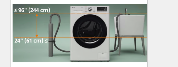
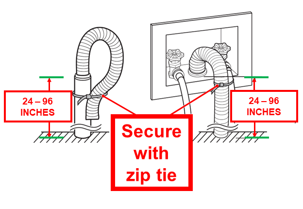
The drain hose should be inserted into the standoff pipe or a laundry sink. The standoff pipe should be between 96” (244 cm) and 24” (61 mm).
The drain hose entering the standoff, or sink, should have a bend at the end of the hose, (usually there will be an elbow bracket forming a bend), and no more than 4” into the standoff pipe.
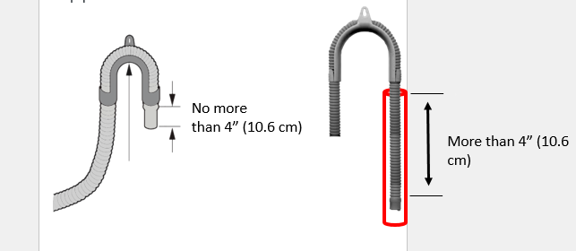
If the drain hose is too deep into the Stand off, more than 4”, it may siphon back and cause an IE error, or cause no, or slow drain issues.
Please check the install guide for your individual machine. These principles will apply to front loads, wash towers, and other select models.
Is the drain filter and pump housing clean?
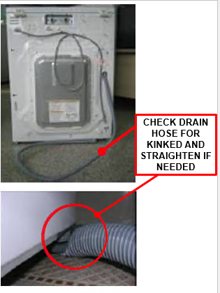
Is the drain hose kinked, twisted, or blocked with debris?
Has the drain hose been installed correctly? No more than 4 inches into the standpipe
Make sure that the drain hose is not stretched, pinched, crushed, or kinked.
Is there a laundry item stuck in the outer tub drain hole or bellows to the pump housing?
Is the air chamber or pressure sensor tube blocked?
- The end of the drain hose should be located a minimum of 24″ and a maximum of 96″above the bottom of the washer.
- For best results, locate the end of the drain hose no higher than 66″ above the bottom of the washer. As the drain outlet is raised beyond 66″ the drain function will be increasingly affected.
- Never create an airtight seal between the hose and the drain with tape or other means. If no air gap is present, water can be siphoned out of the drum resulting in poor wash/rinse performance or clothing damage.
Check and clean the pump filter. Accumulation in the drain filter not only prevents proper drainage, but also will promote bacteria growth and cause odors.The drain filter should be cleaned once a month.
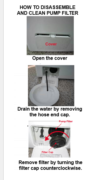
HOW TO DISASSEMBLE AND CLEAN PUMP FILTER. Open the cover. Drain the water by removing the hose end cap. Remove filter by turning the filter cap counterclockwise. Clean the filter. Re-install and close hose cap.

Check the Pump Resistance and Voltage.
Check the harness connection at the drain pump and Main PCB. Is the harness loose or disconnected?
Is the impeller of the pump damaged? Measure the resistance of the pump motor.
The pump should measure approximately
24Vdc BLDC Drain Pump – 1.5~4ohms on each winding. Check gray 3 pin connector white wire, blue wire & sky blue wire.
120Vac Drain Pump – 10 to 20 ohms. Check white 6 pin connector gray wire to blue wire.
Activate the drain pump in test mode. Does the drain pump receive proper voltage?
If not, check voltage at the Main board.
If proper voltage is present at the Main board, suspect a harness issue. Check resistance of pump from Main board to verify the harness is defective or good.
If still no voltage, replace the Main board.
3 PHASE
BLDC DRAIN MOTOR
3 to 5 ohms
On each winding
Pin 1 to Pin 2
Pin1 to Pin 3
Pin2 to Pin 3
SPECIFIC WIRE COLORS WILL VARY PER MODEL

120Vac
DRAIN MOTOR
13 to 17 ohms
SPECIFIC WIRE COLORS WILL VARY PER MODEL
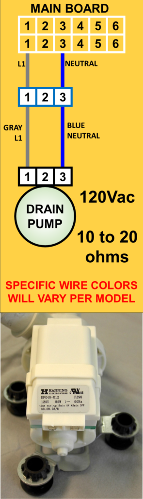
GRAY L1
BLUE NEUTRAL
120Vac
10 to 20 ohms
SPECIFIC WIRE COLORS WILL VARY PER MODEL