Refrigerator
No Power
Click on the Steps below to jump directly to that section:
**NOTICE**
Wiring Colors, Connectors, and Pins will vary by model/product code. Always be sure to download and use the service manual for your specific model.
For Test Mode procedures use this link and input your specific model: https://lgtestmodes.com/
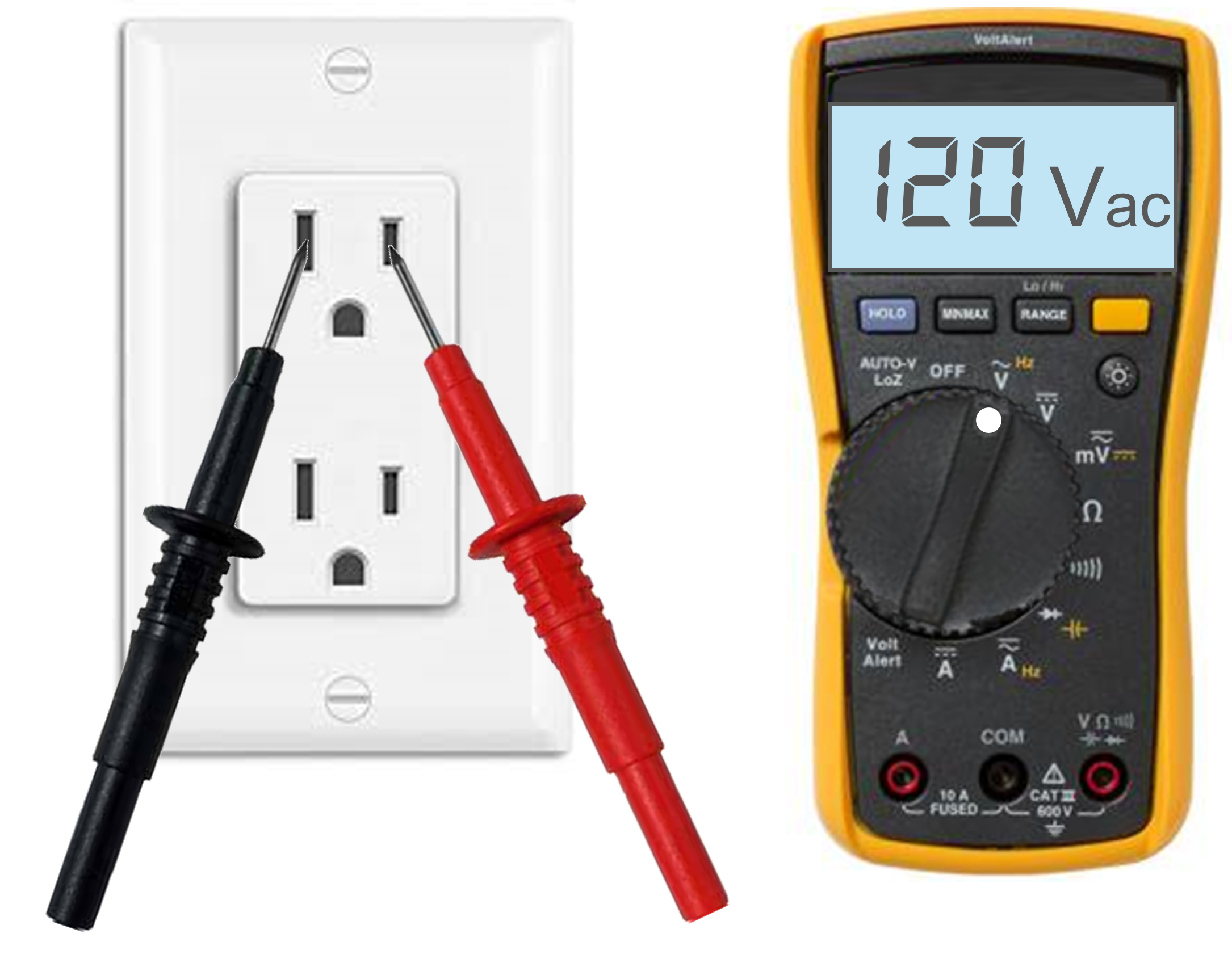
First Check the power source for correct power. Should have 120Vac at the wall outlet across Line and Neutral…
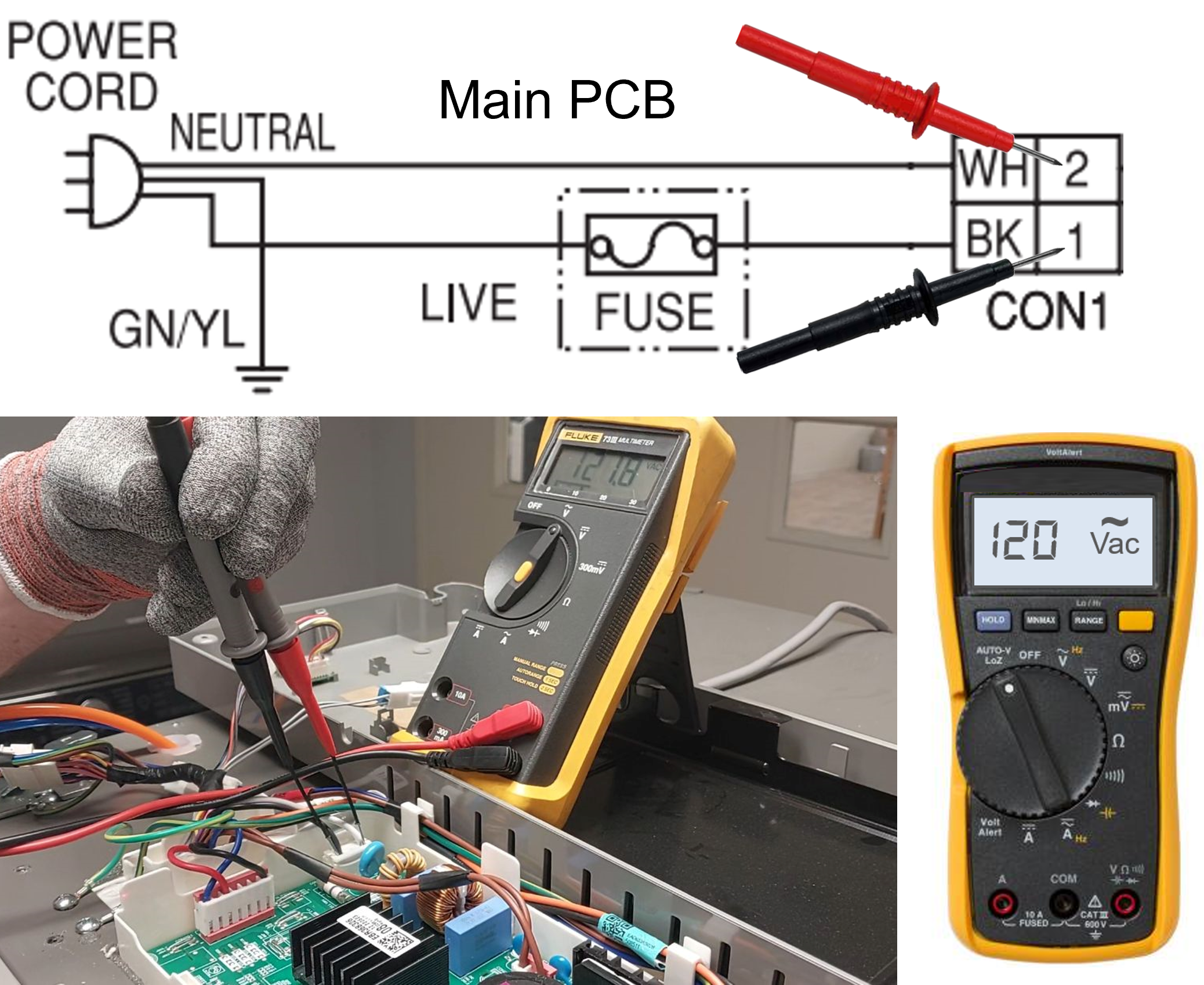
Next, verify you have power at the Main PCB, this will eliminate the power cord being an issue…
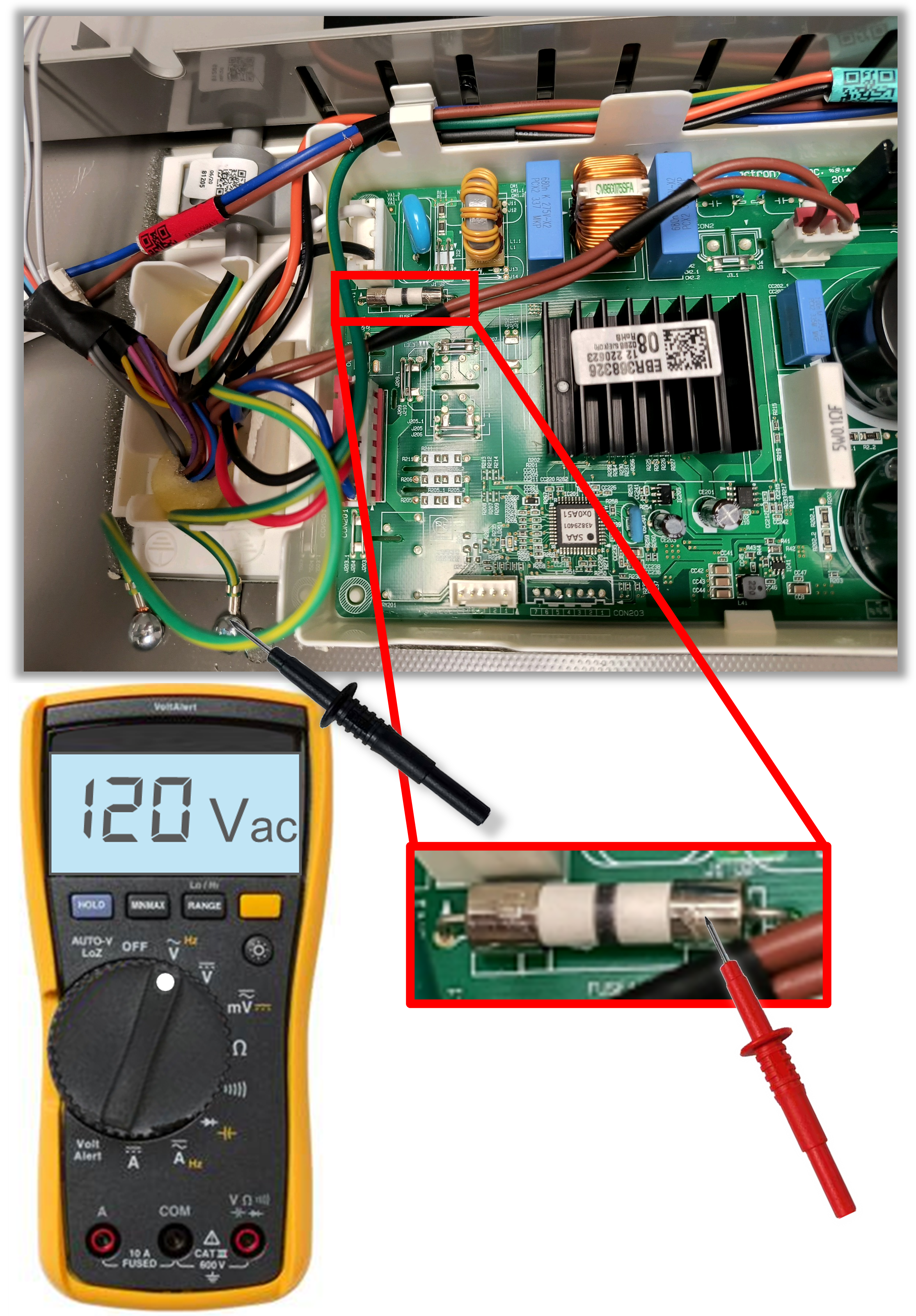
Next, test the AC fuse on the Main PCB to make sure it is closed…
Locate the large fuse located on the Main PCB. Test to make sure the fuse is closed. If good, the fuse will read 0Vac across the fuse and 120Vac from each side to ground.
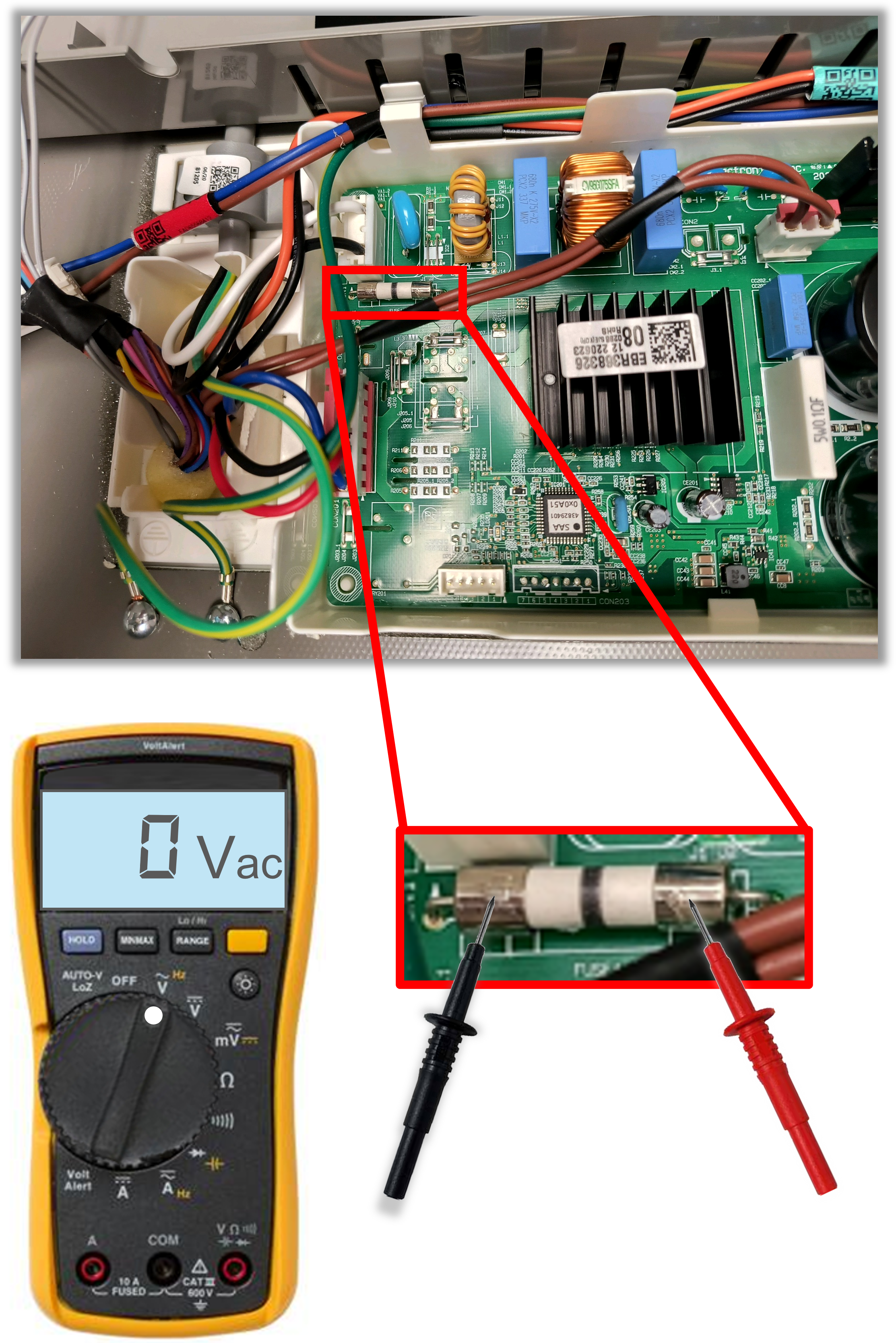
Note: When testing ACROSS a fuse as shown above, if you read 120Vac this means the fuse is open and the fuse/board will need to be replaced.
You will also need to test the AC components to see if anything is shorted that caused the fuse to blow. Do not just assume that it was an outside power surge.
Ohm Test:
-Mullion Heater
-Defrost Heater(s)
-Compressor
-Any other AC components on your specific model. See the Service Manual for exact readings.
Another way to test the fuse… Check each side of the fuse to ground and both readings should be 120Vac if the fuse is good. If you only read 120Vac on one side of the fuse, the fuse is open and once again check your AC components for any shorts.
Test for shorted DC Component
If you have verified there is 120V coming into the Main and the fuse is good but the unit is still dead, then this typically means there is an issue with a DC component loading down the board.
–Hint: Look for a blinking LED on the Main PCB. If you see a 8 Blink code this means there is a shorted DC component that the board is detecting.
-There may not always be a 8 blink code, this is a feature that was added to newer model refrigerators.
-There are many low voltage DC circuits so it can seem overwhelming to try and narrow down where the problem is located. But we have some helpful tips to make this easier…
- Unplug the unit from the wall and disconnect all connectors from the board.
- Locate the connector that contains the Display PCB using the wiring diagram for your unit. Only plug in the connector that contains the Display PCB and the main power and see if the display will light up.
If the display lights, plug in one connector at a time (Disconnect the unit from the wall before plugging in a connector) until the display turns back off. You have now narrowed down to the connector that contains the shorted DC component.
– Note: If the display does not light up during this test, Check for 12Vdc being sent from the Main PCB to power the display.
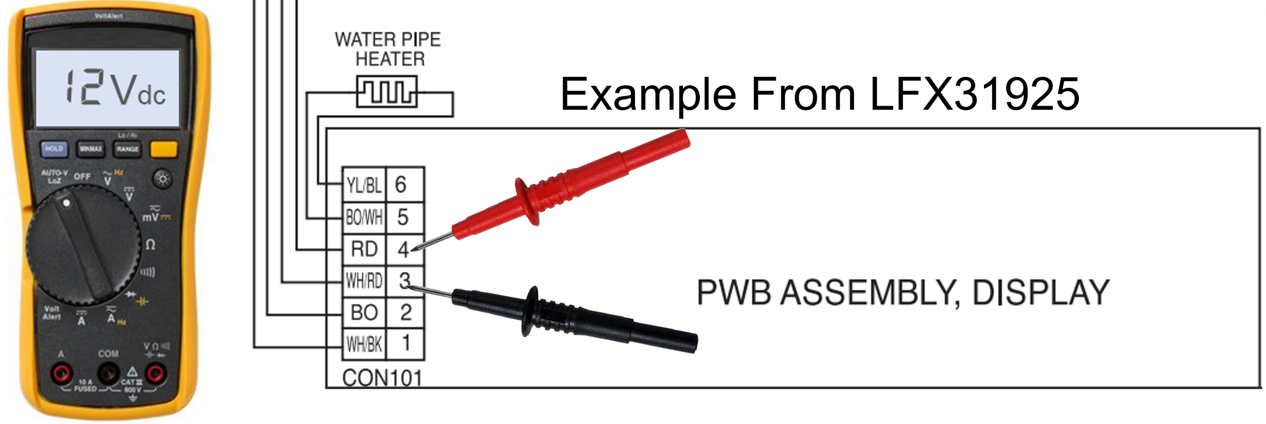
4. Look at your wiring diagram to see what components are part of the connector that is loading down the board. You can either unplug each component one at a time or ohm the component to find the short. Replace the defective part and the unit is repaired.
A few common components the TCC team has found shorted while troubleshooting with technicians on the phone that causes the unit to be dead (these were found using the above troubleshooting method):
- Flow Meter (On Water Valve)
- Knock-On Light PCB (PCB for right glass door with knock feature)
- Icemakers
- Condenser Fan
Check the OLP for the Compressor. (For Models with BLDC Compressors)
If you have a BLDC compressor it will likely have an OLP that will kill power to the unit if it is open.
Even though you have 120V supplied to the unit and the fuse is good… If the OLP is open all voltage output from the Main PCB will be stopped so the unit will appear dead (No lights or any functions).
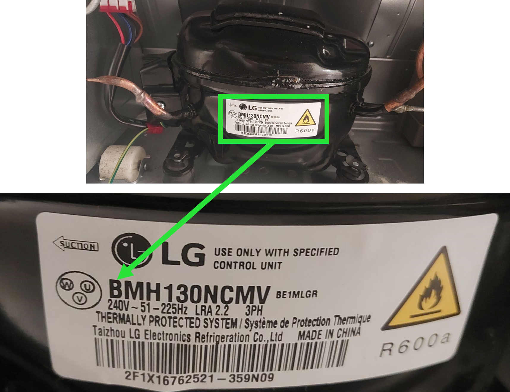
BLDC Compressors can be identified by looking at the Compressor tag. If the compressor Model starts with a “B” its a BLDC Inverter Compressor:
Look at your diagram. If you see a OLP wired to its own two pin connector this is a sign that it will kill power output from the Main PCB if the OLP opens. Here is an example of what you will see on the wiring diagram:
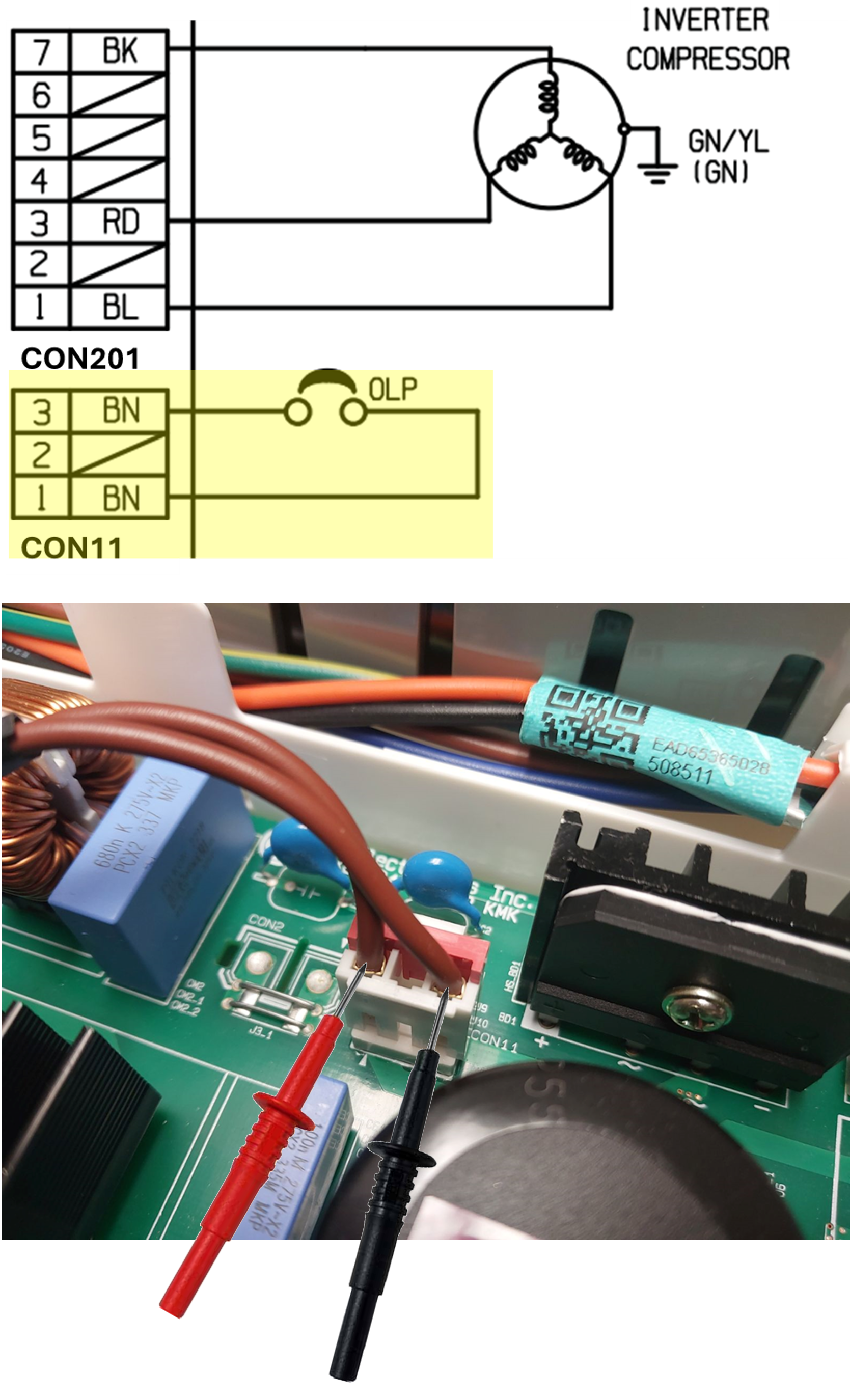
Voltage Test:
If OLP is closed like it should be, you would read 0Vac across the two wires. (This is with 120Vac being supplied to the unit).
If you read 120Vac the OLP is unplugged or open. Check in the machine compartment.
Ohm/Continuity Test:
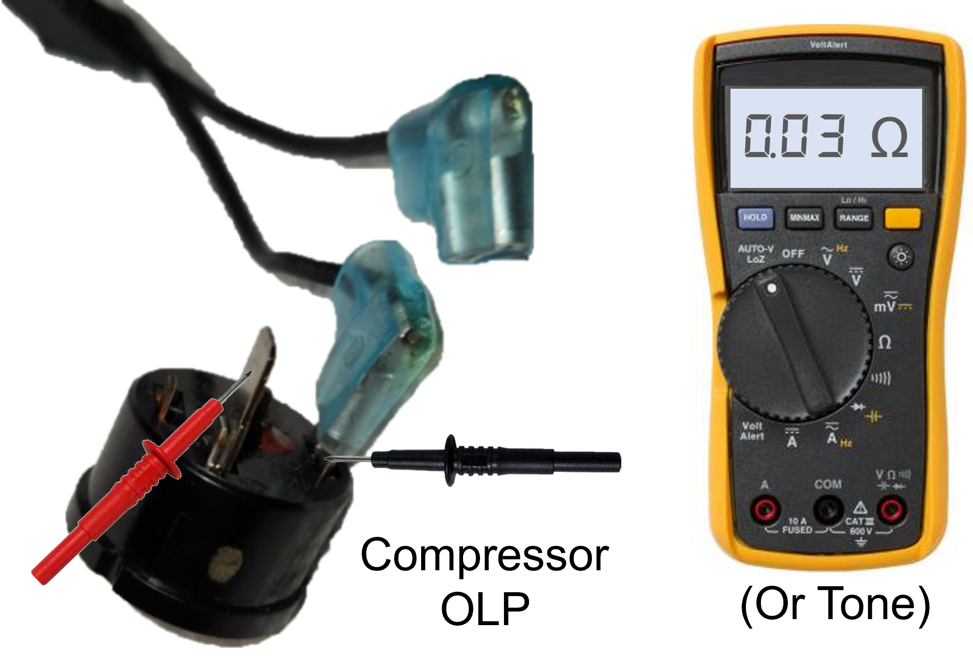
Unplug the two wire connector from the main. The circuit should read closed or beep depending on meter used.
If you read OL or open then the OLP is unplugged or open. Check in the machine compartment.
Below shows testing directly at the OLP:
