Look For An Error Code On The Display
Error codes are displayed on the display to signal that the unit needs your attention. If you see an error code you will need to address the reason for the Error code.
Many times, the customer will report that they can unplug the unit and the dispenser will work properly for a time but will eventually stop. If the unit presents an error code the dispenser functions will be suspended, until error is cleared. Example, if you have an error code If (ice fan) the dispenser won’t dispense water or ice, (if the unit dispenses Water but not ice then the issue isn’t an error code or a door switch issue). Once you address the Ice Fan, (or your specific error code), issues the dispenser will operate properly.
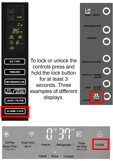
Ensure Control Lock Is Turned OFF
If you do not see an error code, check to make sure the Control Lock is not engaged. Look to see if the locked padlock icon is illuminated on the panel. If it is, press and hold the lock key for 3-5 seconds to unlock, and then try dispensing ice again.
Listen For A Humming Sound
Press the dispenser lever down again and listen for a humming noise. If the unit makes a humming noise when trying to dispense ice, make sure there is ice in the ice bin.
Check The Door Switches
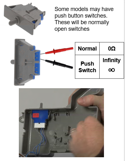
If the dispenser does not hum when trying to dispense, one or both of the door switches may be disconnected. The dispenser will not operate if the unit thinks the door is open. The door switches control the unit’s interior lights–if the door sensor is a push switch, push it in to make sure the lights turn off. Check the push switch on both doors.
If there is no push switch, then the unit is using magnetic reed switches located in the door top hinge covers. Hold a magnet over the reed switch at the top left hinge cover and see if the lights go out. Be sure to check both doors–the other sensor is at the top right hinge cover. If the interior lights do not turn off when you test the door switches, this can indicate a loose connection underneath the top door hinges or possibly a defective reed switch.
If the unit is new and it’s just been installed, check under the hinge covers and make sure all connections are proper and secure if the unit is older and has been working and the doors have not been removed then proceed with troubleshooting.
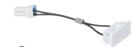
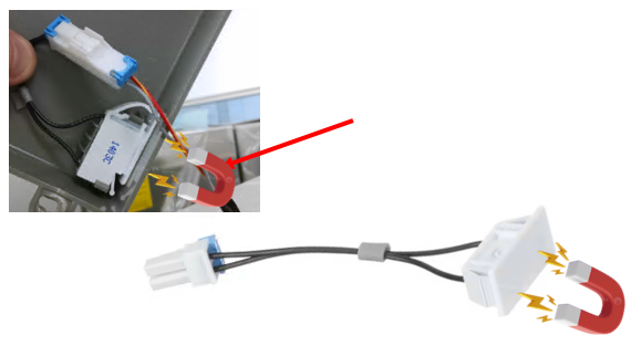
Some models will have Reed door switches (magnetic).
These will also be normally open switches.
When a magnet is placed over the door switch you should read continuity on your meter, and no resistance when the magnet is removed. Make sure the switch is installed in the hinge cover properly and connected properly.
The magnet is in the door opposite the reed switch. Some are replaceable and some require a door replacement if the magnet has weakened or moved out of position.
Check for Loose Connections
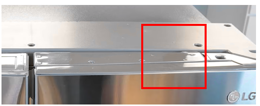
Under Door Hinge
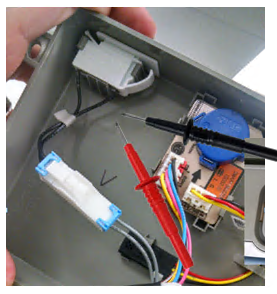
Using a Phillips screwdriver, remove the door hinge cover on one side. Check the connections one at a time by unplugging and plugging them back in. Repeat the process with the other door hinge, removing it and checking the connections one at a time.
Then check the dispenser again.
Remember the dispenser will not activate if the Main PCB thinks the door is open. You may have to put a magnet over the door switch if you have the cover off to test the PCB for voltage.
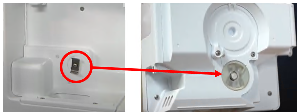
Place a small magnet on door switch here to check the switch continuity.
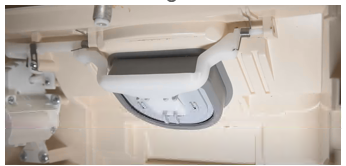
Check auger motor, dispenser Ice flap motor
The auger motor is located behind the ice bucket, make sure you hear it being energized. If it is being energized, then make sure the flap is opening.
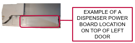
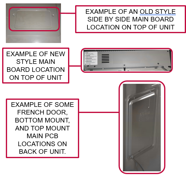
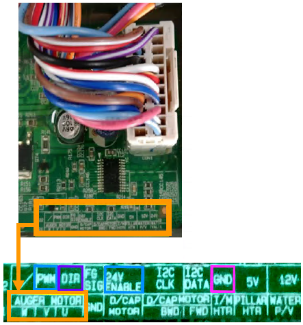
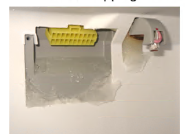
Board locations
Auger motors will be getting voltage from the main board or the dispenser power board on top of the left door.
Main boards are either on the back of the unit or on top of the unit.
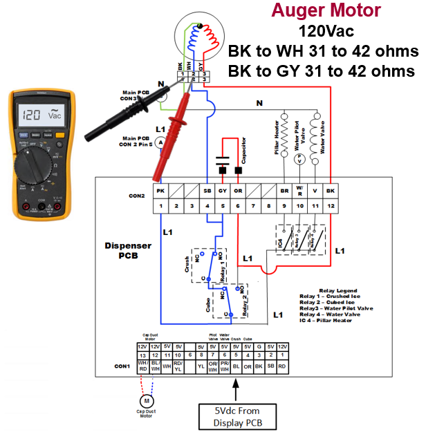
Auger Motor 120Vac
Sequence of operation.
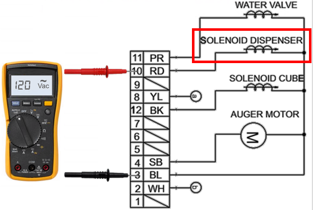
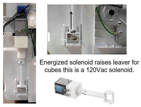
Some earlier models used a solenoid to open the Cap duct, and it was activated with 120Vac.
Example from LSC27910:
Auger Motor
120Vac
BK to WH 31 to 42 ohms
BK to GY 31 to 42 ohms
Sequence of operation.
120Vac supplied to Auger motor Black to White. Auger motor turns and engages the ice bucket assembly and turns the auger to produce the desired ice type. (Your issue could be as simple as reinstalling the ice bucket as it may not be seated correctly in the ice room).
If the Auger turns but no ice dispensed, check for clumped ice in the ice bucket.
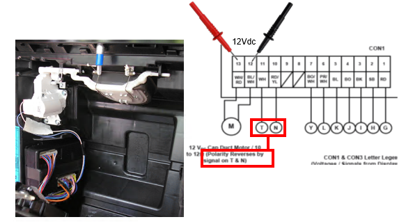
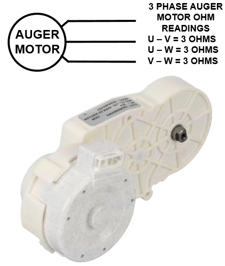
24 Vdc operated Auger
Some newer models use a 3 phase 24V DC Auger Motor.
Example from LFXC22596
Notice no wire colors were given because wire colors will vary by model but this should help you troubleshoot this circuit regardless of wire colors or model#.
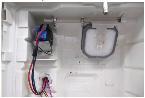
Older Solenoid operated Auger
Some older models use a solenoid to activate the ice type.
Pictures show the default CRUSHED position.
Clumping Ice
If the Auger motor is turning and you have ice in the bucket, but none dispenses, check for clumping ice. The leading cause of this is usually a door left open.
If the clumped ice is only on top it could be the fill tube for the ice maker is dripping or overfilling.
If the clumped ice is only on bottom it could be the flap for the Dispenser isn’t sealing letting warm air up into the ice bucket. Check the seal with a light.
If the customer doesn’t use the ice very much, and the unit cycles through several defrost cycles, this can also cause the clumping.
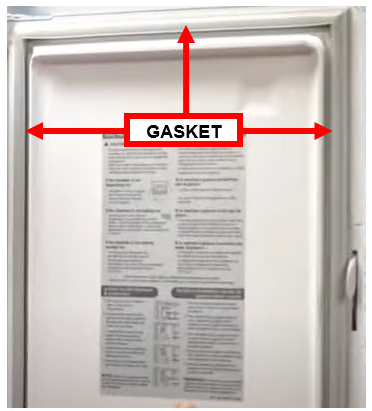
Also check the Beta gaskets that allow air from the freezer into the ice room. If they’re damaged this will allow warm air into ice room, causing clumped ice as well.
Check the ice room door gasket. If its damaged this will cause clumped ice as well, as it allows warm air into the ice room.
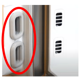
Dispenser Switches
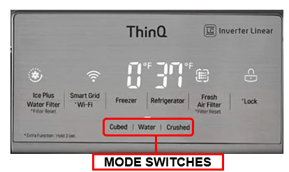
Check the Ice dispenser switches, paddles. If your unit has a single switch for Ice and water, and the unit will dispense water, the switch is good, the display board that switches modes is bad. Check your unit’s schematic or parts breakdown to verify.
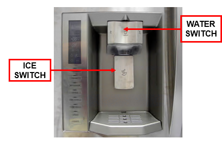
Two independent switches type
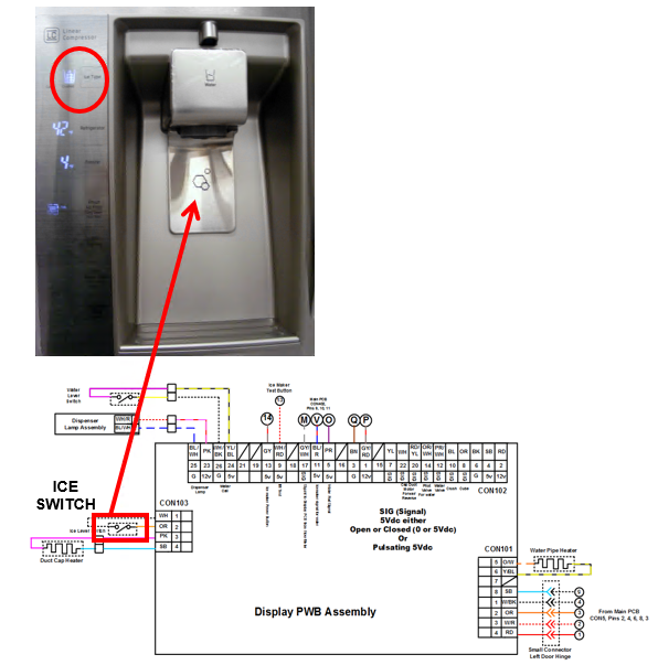
Ice Switch
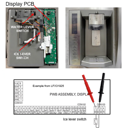
Check the ICE dispenser switches, paddles. If your unit has a separate switch for Ice and a separate switch for water, and the unit will dispense water, but not ice the switch could be the issue. Depending on your model of dispenser it may be easier to check the switch from the board that controls it. Check your unit’s schematic or parts breakdown to verify location.
5Vdc should be present from the PCB without pressing ice lever. If not, the PCB is bad. Voltage should go away when switch is pressed, you have just verified both the PCB and the switch.