Gas Dryer
Not Drying
Click on the Steps below to jump directly to that section:
**NOTICE**
Wiring Colors, Connectors, and Pins will vary by model/product code. Always be sure to download and use the service manual for your specific model.
For Test Mode procedures use this link and input your specific model: https://lgtestmodes.com/
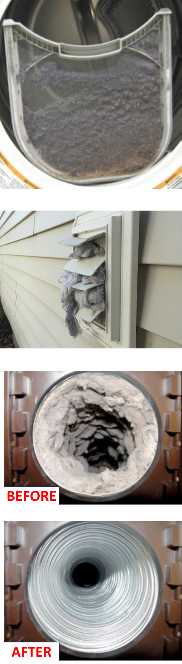
If your LG dryer is taking too long to dry your clothes or your dryer is not heating properly this is likely due to a blockage to the dryer’s airflow, which will make dry times longer than normal. Airflow blockages can be caused by an obstruction in the duct work or lint build-up on your lint screen.
normal dry level option if the complaint is too long of a dry time. Check and clean the Lint Filter, Vent, and Vent exit at the outside of the home. Also check the duct for blockage and if cleaning is needed then have the customer clean out the duct or have a professional duct cleaning service take care of this repair procedure.
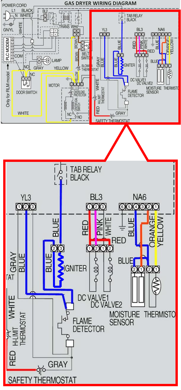
GAS DRYER IGNTION STEPS
To get gas ignition the dryer motor turns and the main board performs 3 tasks.
1) Closes the Black Relay to place the L1 side of the 120 VAC on blue wire to igniter.
2) Verifies Flame Detector Switch is closed using YL3, pins 1 & 2, GRAY & BLUE wires.
3) Places >90 VDC on DC Valve 1 (BL3, pins 1 & 2, Red to Pink) of the gas valve.
Following the successful completion of tasks 1 & 2, current will begin to flow through the igniter circuit. The radiant heat from the igniter will reach sufficient temperature to open the normally closed flame detector switch. (The opening temperature for the flame detector is approximately 370ºF.) With the flame switch open the GRAY & BLUE wires from connector YL3, pins 1 & 2 to the Flame Detector Switch are measuring 120 VAC across the open flame detector. When the flame detector switch opens, the main control board will next place 90 VDC or higher on DC Valve 2 (BL3, pins 1 & 3, Red to White) of the gas valve assembly. With both gas valve solenoids energized regulated gas pressure is allowed to flow through the valve, mix with the primary air, and is ignited by the still glowing igniter. The radiant heat from the burner maintains the Flame Detector Switch in an OPEN condition, keeping 120 VAC across YL3 pins 1 & 2, BLUE to GRAY; this is the flame proving circuit.
As the exhaust temperature rises and the exhaust temperature sensor measures this temperature increase, the control board will remove the 90 VDC or higher on both gas burner valve solenoids when the set point for the selected cycle reaches the designed temperature; the gas valve turns off. Simultaneously, the control board will cycle OFF the igniter circuit by opening the Black Tap Relay.
IF ignition fails to occur, the black tap relay remains closed, the flame detector switch cools & closes at its closing temperature (approximately 320ºF) thereby removing the 120 VAC across YL3 pins 1 & 2. When the flame detector switch closes, the control board removes the >90 VDC to DC Valve 2, stopping gas flow through the valve.
(Note: The control board continues to apply >90 VDC to DC Valve 1)
With the flame detector switch closed, the igniter again heats and the radiant heat from the igniter opens the flame detector switch placing 120 VAC on YL3, pins 1 & 2, BL to GY. The control again applies >90 VDC to DC Valve 2. This allows fuel flow through the gas valve in a 2nd attempt to ignite the fuel / air mixture. The Flame detector switch and YL3 pins 1 & 2 allows the control board to know IF ignition has taken place when the burners’ radiant heat following ignition maintains the Flame Detector in an OPEN condition and 120 VAC is measured across YL3 pins 1 & 2, BL to GY. With failed ignition these steps are repeated again and again until ignition takes place. A common failure has been the DC Valve 1 solenoid.
If the flame detector switch fails open or if the BL & GY wires from YL3, pins 1 & 2 break, or if the YL3 connector is disconnected at the control board, the control board will not apply DC voltage to either gas valve solenoid.
Igniter Circuit:
The neutral side of the line to the igniter travels via the white wire from the line cord, through the closed door switch pins 1 to 2 to motor terminal pin 3. In the motor neutral passes through the centrifugal switch to motor pin 9. From pin 9 of the motor switch neutral continues on a white wire to the Hi-Limit Thermostat, exits on the red wire to the Safety Thermostat, and from there leaves on a GY wire to the Flame Detector Switch. Finally, neutral leaves the Flame detector switch on a blue wire to the Igniter. Reminder: If the flame detector switch is open due to failure, that is 120 VAC is measured across YL3, pins 1 & 2 after the Black Tap Relay closes, the control board will not energize the gas valve solenoids with DC voltage. This becomes the safety proving circuit.
L1 enters the Black Tap Relay on a Black wire and exits the relay on a Blue wire to the Igniter. With L1 & Neutral present on the igniter (120 VAC), amperage increases as igniter resistance decreases.
The measured amperage reaches approximately 4 amps when ignition takes place.
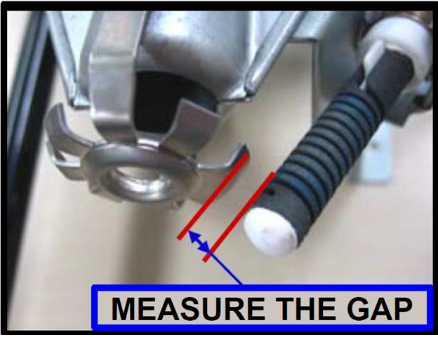
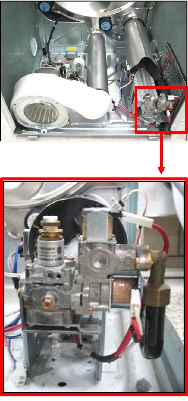
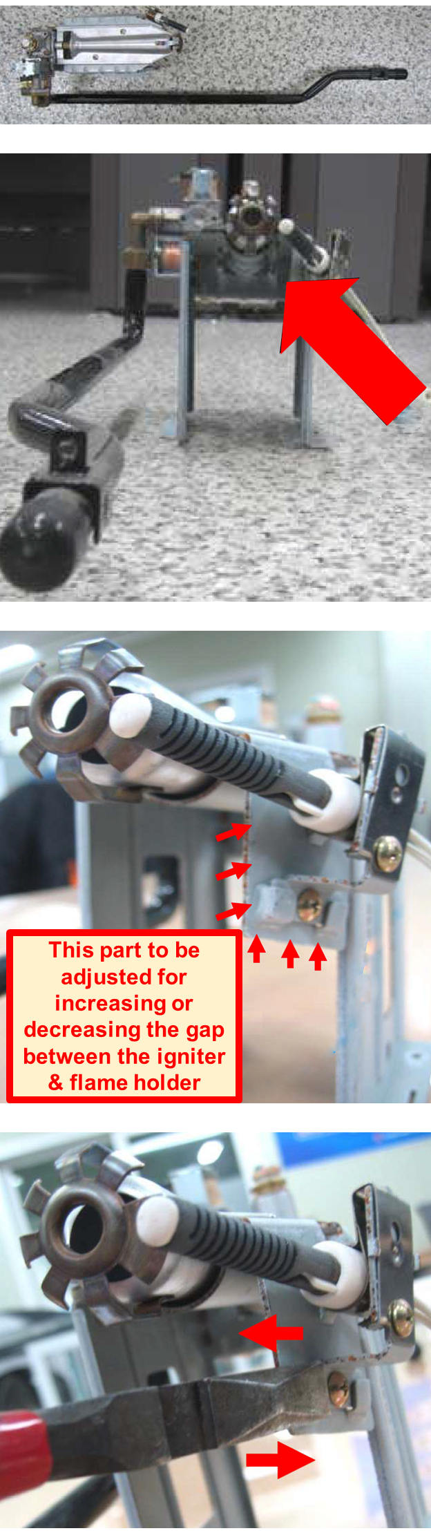
ADJUSTING THE GAP
The distance between the igniter & flame holder should be between 3mm and 6mm (1/8 – 1/4 inch) If the distance is not within this range, adjust it.
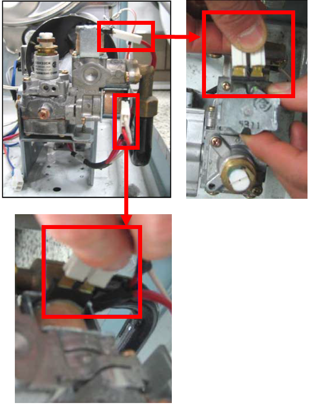
Disconnect two connectors.
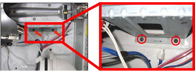
Remove two screws as shown below
Now disassemble the burner assembly by keeping it tilted and pushing it as shown in the pictures. Push to release it from the clamp at the base.
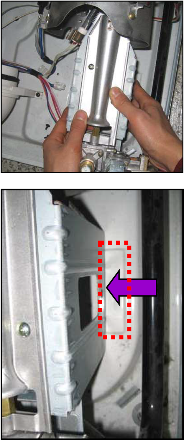
NOTE: THE IGNITER IS FRAGILE! Be careful that it doesn’t break while removing the burner assembly.
Take out the burner assembly
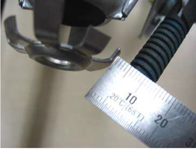
Measure the gap after repairing. It should be within the limit 3mm – 6mm (1/8 – 1/4 inch).
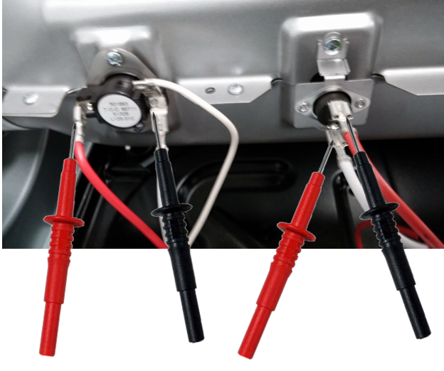
Check the burner thermostats for continuity. If no continuity is measured on any thermostat then replace the thermostat. See picture below of the heater assembly thermostats.
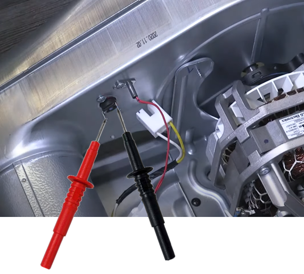
Check the blower thermostat for continuity and if no continuity is measured then replace the thermostat.
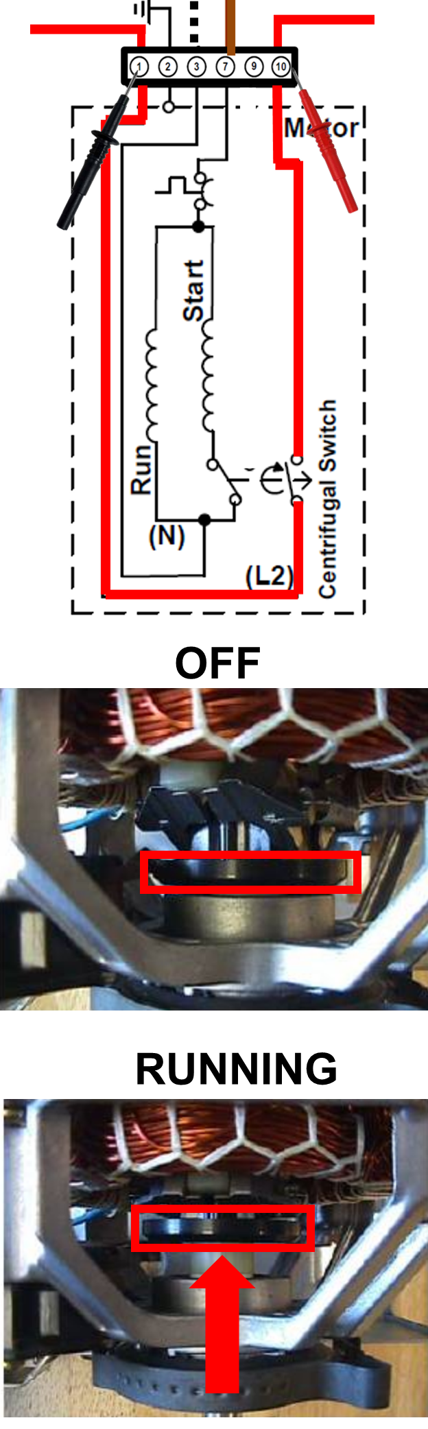
Lastly the centrifugal switch working incorrectly can cause the unit not to heat. (It wont turn on the igniter until the drum is turning).
Unplug the dryer.
Remove the front panel and the drum.
Locate the drum motor and disconnect the motor harness connection. Check continuity on motor terminal pins 1 and 10. Your meter should read no continuity, now push the centrifugal switch collar towards the windings of the motor. Now the meter should read continuity. If the centrifugal switch does not read continuity while pushed in then replace the motor.