TV

OLED TEST PATTERN GENERATOR JIG
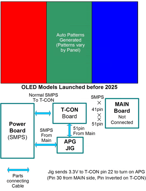
(OLED’s before 2025)
Turns on the OLED’s Rolling Test Patterns for Panel Test
OLED Test Pattern Jig Part Number: RAD33749102
Use this Jig to help determine if a particular Video or Display issue is related to the Panel or the Main Board.
By attaching this Jig is the correct way, the OLED Panel (if provided with power) will generate Rolling Test Patterns on screen.
Note: Part number may change over time, please check GSFS for correct part number when ordering.
This new Jig will assist the Technician with Panel issue diagnostics without the use of the cumbersome attachment of the Smart TV Test Jig and Multi Gender Board. Three simple cable disconnects and Two simple connections required.
IMPORTANT: The Power Supply must be producing its normal output voltages. Both to the MAIN board and the T-CON Board.
(1): NO AC POWER APPLIED: DISCONNECT
THE FOLLOWING CONNECTORS:
On the MAIN Board: Power Supply Connector
and the 51pin Cable going to the T-CON.
On the T-CON Board: disconnect the 41pin
Connector, (Can be removed from the MAIN
Board, but easier from the T-CON).
(2): JIG CONNECTIONS:
P1: Insert the Power Supply connector removed
from the MAIN Board into P1 on the Jig.
J1: Insert the 51pin cable from the T-CON into J1.
(3): APPLY AC POWER: to the TV and the Panel should display Patterns On Screen. (Note1: RED LED should be glowing RED).
(Note2: Power Supply must be producing all voltages, Main Voltages and T-CON Voltages).
NORMAL PATTERNS SERVICE GUIDE:
Rolling Test Patterns Produced (*AGP):
If the Jig produces normal patterns on the Module, the MAIN Board should be replaced.
Note: Before replacing the MAIN Board, inspect the Vx1 Cables. Look for any damage, or peeling connectors.
Confirm the Power Supply is producing normal MAIN Board Voltages, 12VM and 20VS~24VS.
NO PATTERNS SERVICE GUIDE:
Panel Does Not Produces Rolling Test Patterns (*AGP):
If the Jig does not produces normal patterns on the Module, the MODULE (PANEL) should be replaced.
Note: Before replacing the MODULE check following:
Inspect the Cables going to the Panel. Look for any damage, or peeling connectors.
Confirm the Power Supply is producing normal T-CON Voltages, 20VD~24VD and 12VT.
Check for Red LED on Jig is illuminated. If not on, Confirm the Power Supply is producing normal MAIN Board Voltages, 12VM and 20VS~24VS. (RED LED only monitors 12VM)
Read Power Supply Label to confirm what voltages should be produced.
*APG: Auto Pattern Generator
Some Patterns are Color Bar Type,
Some complete screen changes Colors starting from Full White, ending in Black.
Some are a bar that sweeps from Left to Right of different colors.
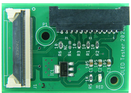
OLED Test Pattern Jig Simple Hook Up Picture:
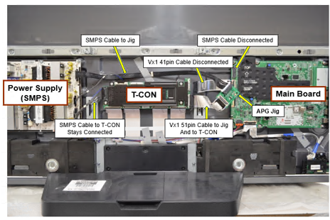
(1): Disconnect the Following Connectors: MAIN Board: Power Supply Connector and the 51pin Cable going to the T-CON.
On the T-CON Board: disconnect the 41pin Connector.
(2): APG Jig Connections: Insert the Power Supply connector from the MAIN Board into P1. Insert the 51pin cable from the T-CON into J1.
Apply AC Power to the TV and the Panel should product Patterns On Screen. (Note1: RED LED should be glowing RED).
(Note2: Power Supply must be producing all voltages, Main Voltages and T-CON Voltages).